What is WSPR?
WSPR — pronounced "whisper" — stands for Weak Signal Propagation Reporter. It is a digital mode developed by Nobel Prize-winning physicist Joe Taylor K1JT, designed to transmit an extremely narrow-bandwidth signal carrying just your callsign, Maidenhead locator, and transmit power. The signal is so efficiently encoded that receiving stations across the world can decode it even when it is completely inaudible to the human ear.
The beauty of WSPR is that it turns your station into an automatic propagation beacon. Once running, it transmits every two minutes on a rotating schedule of bands, and receiving stations upload their spots to WSPRnet.org — giving you a real-time picture of which bands are open, how far your signal is travelling, and what the propagation conditions are like at any given moment. Leave it running overnight and wake up to a map dotted with spots from across the globe.
The Kit — QRP Labs Ultimate3S
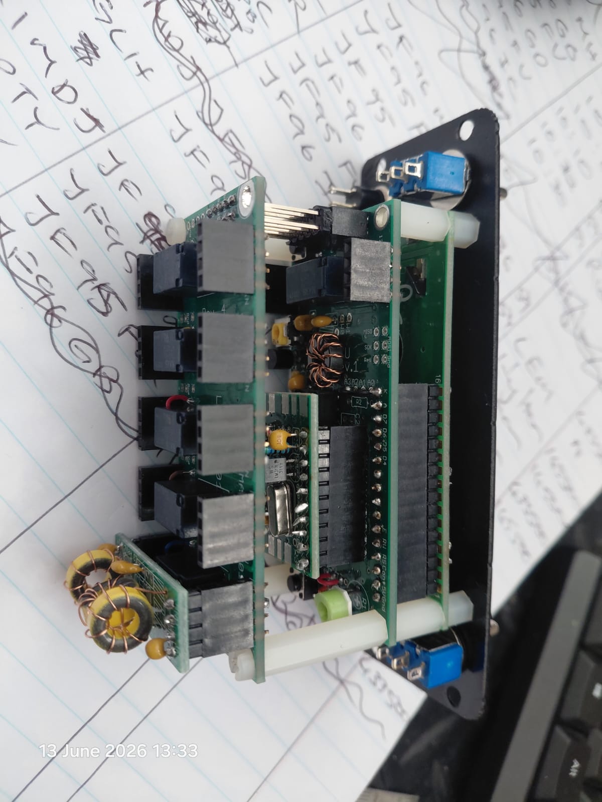
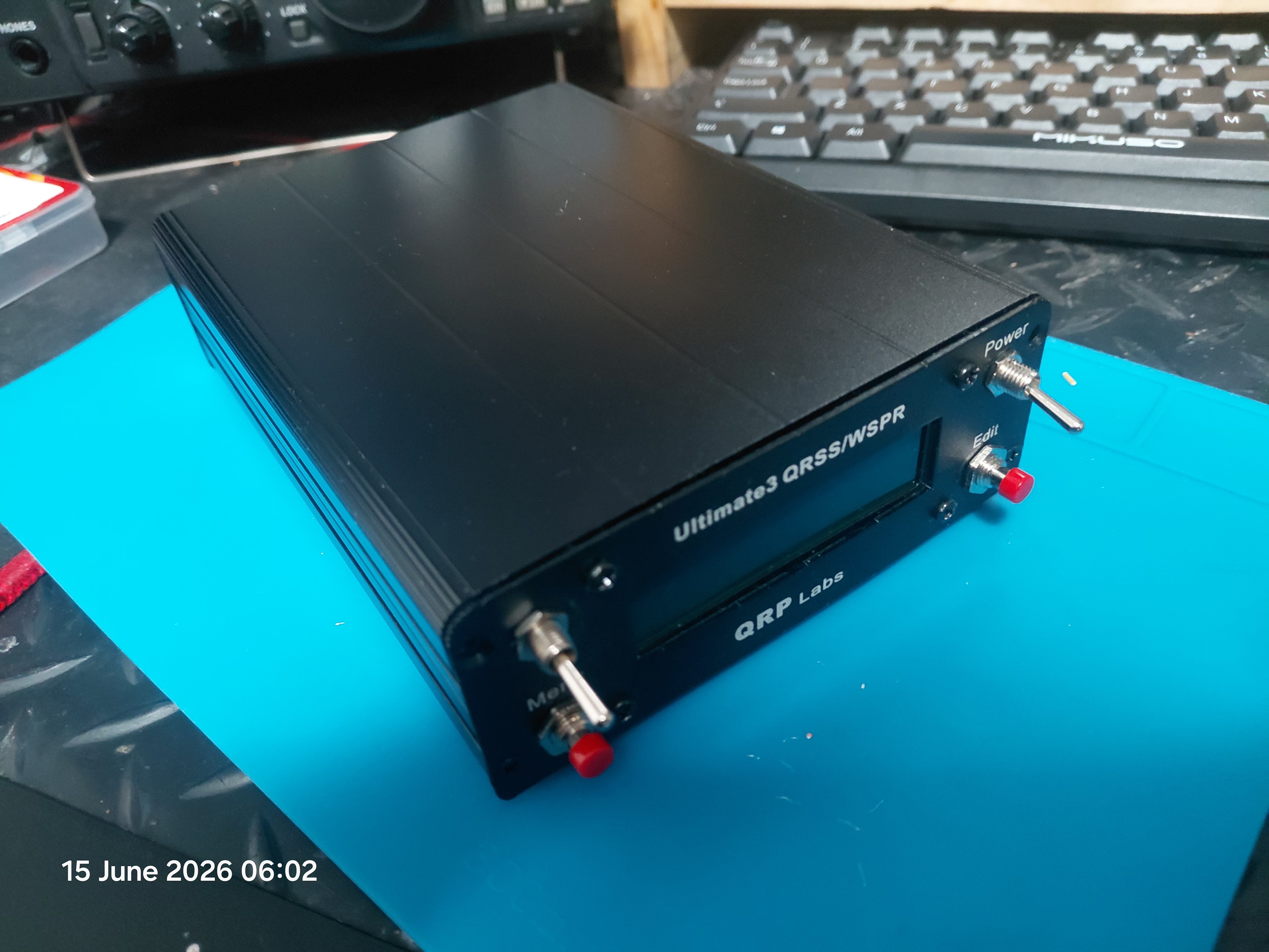
The heart of this build is the QRP Labs Ultimate3S (U3S) — a remarkably capable little kit designed by Hans Summers G0UPL. At its core it is an AVR microcontroller driving a Silicon Labs Si5351A clock synthesiser, which generates the WSPR signal with rock-solid frequency accuracy. The kit supports up to six low-pass filter modules on a relay-switched board, allowing it to sequence automatically through multiple HF bands.
My build consists of:
U3S main board with Si5351A synthesiser
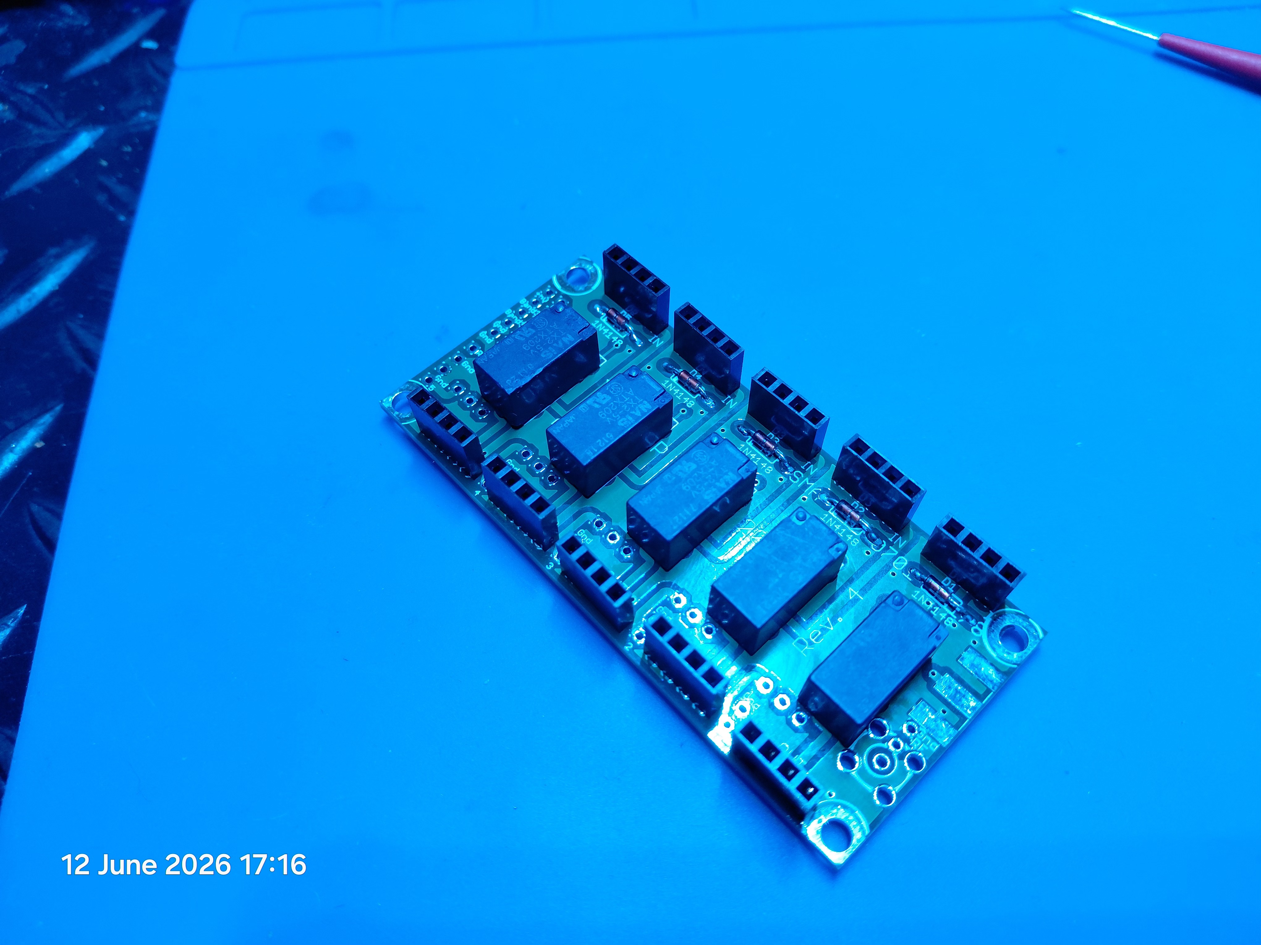
Relay-switched LPF board (six slots)
Six individual low-pass filter modules — 6m, 10m, 15m, 20m, 30m, 40m
QRP Labs QLG1 GPS receiver — for frequency calibration and accurate timing
Official QRP Labs aluminium enclosure with DE9S rear connector for GPS
Output power is approximately 200mW (23 dBm) — more than enough to be spotted globally on the lower HF bands under reasonable propagation conditions.
Building the Low-Pass Filters
Each band requires its own low-pass filter module to clean up the Si5351A output and remove harmonics before the signal reaches the antenna. These are wound on T37-6 (yellow) toroid cores — six filters, each with three inductors and four capacitors.
The toroid winding is the most time-consuming part of the build. Each pass through the centre hole counts as one turn. The winding specifications for my six bands are:
Band
L1 turns
L2 turns
L3 turns
Core
6m
7
8
7
T37-6 (yellow)
10m
10
11
10
T37-6 (yellow)
15m
12
14
12
T37-6 (yellow)
20m
16
17
16
T37-6 (yellow)
30m
19
20
19
T37-6 (yellow)
40m
21
24
21
T37-6 (yellow)
A jeweller's loupe is essential for inspecting solder joints on the small PCBs. The enamel on the wire ends must be burned off completely with a hot iron — hold it on the tinned pad for 7 to 8 seconds until the solder flows cleanly. A continuity check across each toroid with a DMM after winding confirms a good connection before the filter goes onto the board.
Label each toroid as you wind it. They are identical in appearance once wound and very easy to mix up.
LPF Slot Assignment
The relay board has five slots (1 to 5), with an additional slot on the main U3S board (slot 0). The critical rule is that the highest frequency filter must always be in slot 1, nearest the RF output, because the relay board switches filters in sequence and the first slot is always in the signal path.
Slot
Band
Frequency
0 (main board)
40m
7,040,100 Hz
1
6m
50,294,500 Hz
2
10m
28,126,100 Hz
3
15m
21,094,600 Hz
4
20m
14,097,100 Hz
5
30m
10,140,200 Hz
Configuration — Getting the Callsign Right
The U3S menu system is navigated with two buttons. Getting the callsign entered correctly took some persistence — the firmware requires the callsign to be terminated with the Enter symbol (a return arrow character) immediately after the last letter, with absolutely no trailing spaces. Even one space after "ZS1ZZ" produces an Error 1 Callsign message and the beacon will not transmit.
Parameter
Value
Callsign
ZS1ZZ
Locator
JF95fx
Power
23 dBm
Mode
WSPR
Frame
2 minutes
GPS Mode
2 (rising edge PPS)
Baud
9600
Cal Step
10 (coarse) → 1 (fine)
Running Without GPS — The First Tests
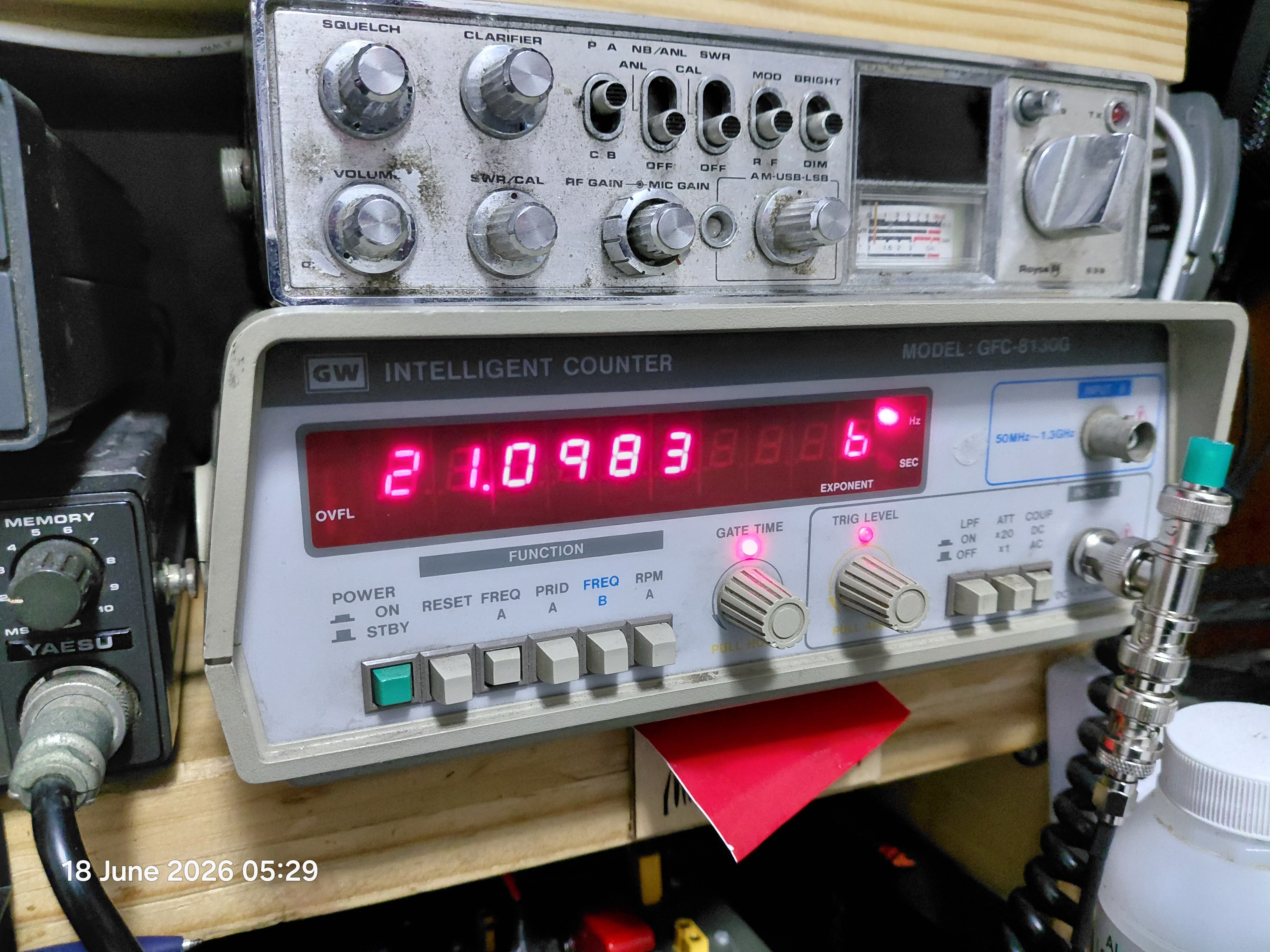
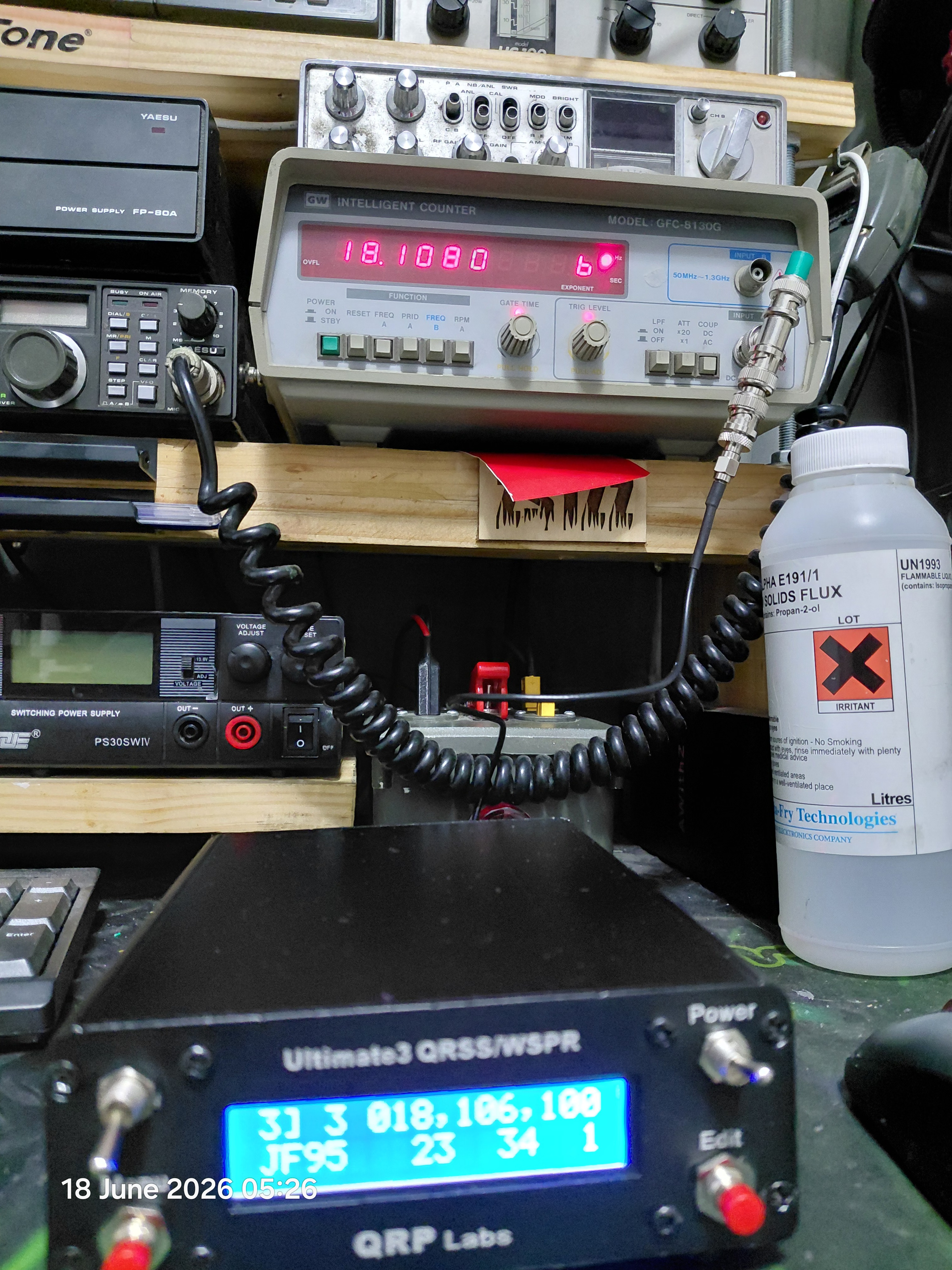
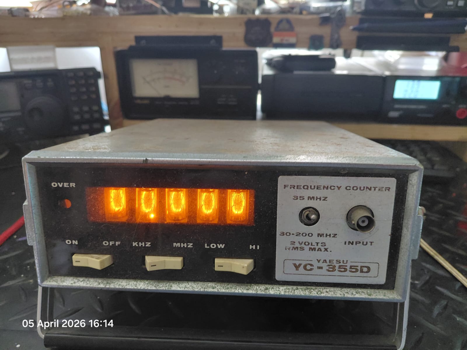
The DE9S connector needed to connect the QLG1 GPS unit was not in the parts bin, so the beacon ran for several weeks without GPS in Mode 0 with manually set time. Frequency verification was done using a GW Instek GFC-8130G frequency counter — frequencies came out approximately 2 kHz off across all bands, which is exactly what you expect from an uncalibrated crystal oscillator. Perfectly usable for testing, but not accurate enough for WSPR spots to be accepted reliably by the network.
Building the QLG1 GPS Receiver
The QLG1 is a kit in its own right — a Mediatek chipset GPS module on a large PCB with a custom-tuned 25×25mm patch antenna. The large ground plane (64×64mm) gives it 7.5 dBic more antenna gain than a typical small GPS module, making it highly sensitive.
Construction is straightforward with no SMD components. Key points to watch:
IC1 (74ACT08) orientation — align the dimple with the silkscreen
LED orientation — cathode (flat, short leg) goes into the hole nearest the PCB centre
Battery polarity — the 3V rechargeable lithium cell's positive pin (top of battery) goes into the "+" hole. Getting this wrong even temporarily can damage the RF module
Ground plane solder joints — the double-sided ground plane dissipates heat aggressively. Use extra heat and solder the non-ground pin first to anchor the component, then tackle the grounded pin
The kit includes two 0.1µH axial inductors (L1 and L2) in series with the +5V and GND supply lines. These are easy to miss in the parts bag as they look similar to resistors. Without them the supply voltage never reaches the IC and the LEDs will not light. If you find your QLG1 showing less than 2V at the logic IC with nothing lighting up — check L1 and L2 first. Wire jumpers work for initial testing; replacement inductors can be wound from 7–10 turns of 0.3–0.4mm enamelled copper wire on a 3mm former.
GPS Wiring — The DE9S Connector
The QLG1 connects to the U3S via the rear-panel DE9S connector using a four-wire cable. The colour code for my cable:
Signal
Wire Colour
U3S Header
QLG1 4-pin
+5V
White
+5V
Pin 1 (top)
GND
Blue
GND
Pin 2
Data
Yellow
RxD
Pin 3 (TXD on GPS side)
Timing
Black
PPS
Pin 4 (bottom)
Note the cross-connection on the data line — the GPS transmits serial data (TXD) which the U3S receives (RxD). This is standard serial convention but catches people out regularly.
The QLG1 4-pin connector has no silkscreen labels on the PCB — the order is confirmed in the assembly manual as +5V, GND, TXD, 1PPS from top to bottom. The cable shield connects to GND at the U3S end only — not at the QLG1 end — to avoid ground loops.
First Light with GPS
On a rainy winter Sunday evening in Wynberg, with a Cape storm rattling the shack windows, the GPS was connected for the first time. Power on — red LED on the QLG1 lit immediately. Yellow LED began pulsing as serial data came through from the GPS module. Within a few minutes the green LED was flashing once per second — satellite lock acquired.
The U3S display confirmed what we wanted to see:
01 0 007,040,100
JF95 23 88 0
Locator JF95 confirmed automatically from GPS. Power 23 dBm. Frequency 7,040,100 Hz. The beacon is GPS-locked and transmitting.
Calibration settings restored: GPS Mode 2, Baud 9600, Cal Step 10 for initial coarse lock, then reduced to Cal Step 1 for fine calibration. The frequency counter confirmed the beacon was now spot-on frequency across all six bands.
The GPS Goes Outside
The QLG1 is mounted outdoors in a weatherproof PVC enclosure on a fence post approximately 2.5 metres from the shack, connected back via a run of unshielded communications cable. This length keeps the GPS well clear of any RF from the beacon while remaining short enough to avoid the cable becoming a resonant antenna on the HF bands. Cable entry into the shack is via proper cable glands.
With the patch antenna facing skyward and a clear view of the sky, satellite acquisition is fast and the lock is solid. The beacon now runs 24/7, cycling through all six bands automatically.